How to connect MAAS networks
You can easily manage the basic networking elements of MAAS, including subnets, fabrics, VLANs, spaces, IP ranges, machine interfaces, and proxies. This section shows how to access and edit these elements.
This article will help you learn:
- How to manage MAAS network elements
- How to manage machine interfaces
- How to manage proxies
- How to set up Network Time Protocol (NTP)
How to manage MAAS network elements
This section will show you:
- How to enable network discovery
- How to toggle subnet management
- How to access the main networking view
- How to display the subnet window
- How to view the subnet summary
- How to view utilisation
- How to manage static routes between subnets
- How to view reserved ranges
- How to view used IP addresses
- How to set up a bridge with MAAS
- How to set up a bridge with netplan
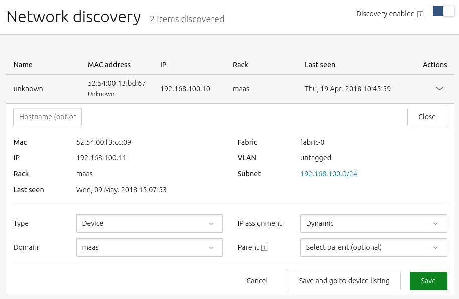
How to enable network discovery
Network discovery can be disabled or re-enabled using the switch on the Network discovery dashboard.
How to toggle subnet management
To disable (or re-enable) subnet management, use the following procedure:
-
Navigate to the ‘Subnets’ page and select the subnet.
-
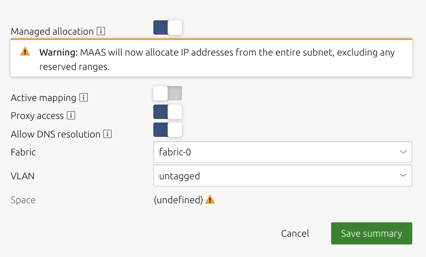
Press the ‘Edit’ button to allow changes; the ‘Managed allocation’ field will become a slide switch.
-
Click the label (or the switch icon itself) to toggle between enabled (dark blue) and disabled (grey).
-
Click ‘Save summary’.
The following screenshot illustrates this process.
How to access the main networking view
To access the main networking view visit the ‘Subnets’ page:
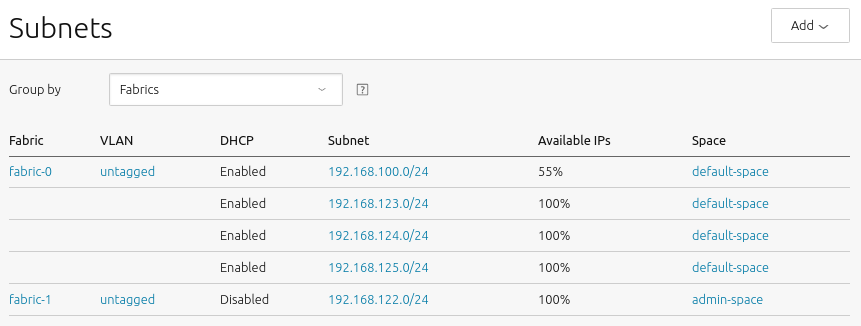
This main view can also be filtered either by fabrics or by spaces through the use of the ‘Group by’ drop-down.
How to display the subnet window
Clicking a subnet (here 192.168.100.0/24) will display its detail screen, which contains several sections, described below.
How to view the subnet summary
The Subnet summary section is the largest and most complex of the subnet configuration screens:
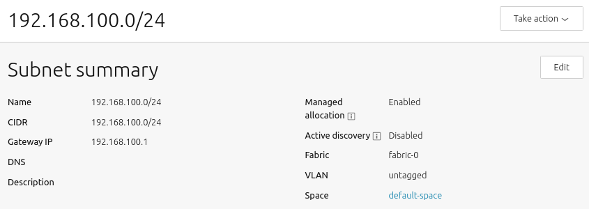
This screen presents the following configurable options:
-
Name: Subnet names can be any valid text string. By default, they are named with the CIDR of the subnet itself.
-
CIDR: This is the address parameter for the subnet. In keeping with standard CIDR notation, the number of bits of the prefix are indicated after the slash.
-
Gateway IP: This is the address of the default gateway for your subnet, which is the IP address that transfers packets to other subnets or networks. Typically, this is simply the first IP address in a block of addresses (the
.1address). -
DNS: This is the address of a DNS (domain name server, or simply “name server”) for your subnet. It’s optional, but can be configured if desired.
-
Description: This field represents free form text that you can enter to describe your subnet, as needed to keep important notes attached to the definition of the subnet.
-
Managed allocation refers to the ability of MAAS to completely manage a subnet.
-
Active mapping instructs MAAS to scan the subnet every 3 hours to discover hosts that have not been discovered passively.
-
Proxy access instructs MAAS to allow clients from this subnet to access the MAAS proxy.
-
Allow DNS resolution allows subnet clients to use MAAS for DNS resolution.
-
Fabric: This field allows you to set the subnets fabric.
-
VLAN: This field allows you to set the subnets VLAN.
-
Space is presented for clarity, though spaces are managed at the VLAN level.
This section of the subnet page presents metrics regarding address usage by this subnet.
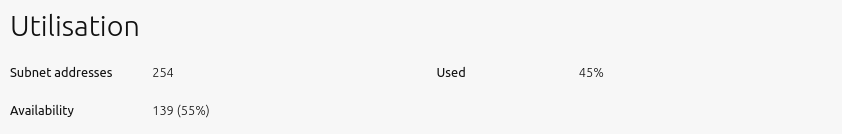
‘Subnet addresses’ shows the total number of addresses associated with the subnet, here 254. ‘Availability’ shows how many of those addresses are unused, and therefore “available”, here 189, which corresponds to a percentage of roughly 74% of the total. Finally, ‘Used’ shows the percentage that is used, here roughly 26%.
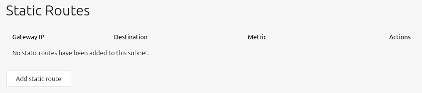
How to manage static routes between subnets
To create a static route:
-
Click the ‘Add static route’ button to reveal the edit pane.
-
Enter a Gateway IP address.
-
Select a destination subnet from the ‘Destination’ drop-down list.
-
Edit the routing metric value if needed.
-
Click ‘Add’ to activate the route.
Routes can be edited and removed using the icons to the right of each entry.
The reserved ranges section of the subnet screen looks like this:
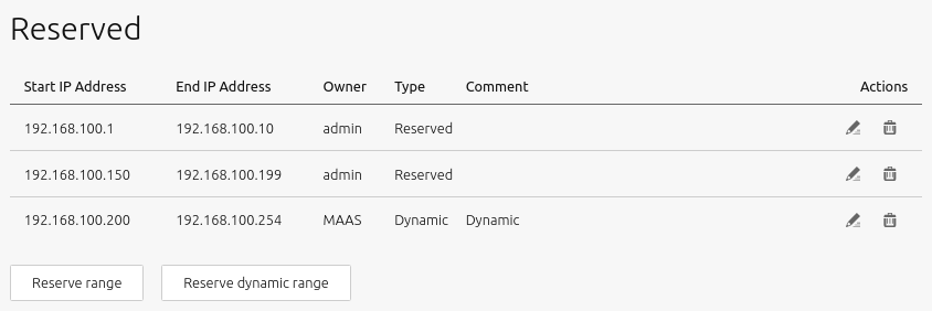
More details and instructions regarding these ranges can be found in IP ranges.
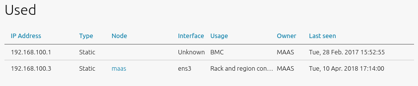
This section displays hosts (including controllers) associated with the used addresses along with related bits of host information.
How to set up a bridge with MAAS
At various times in your MAAS network, you may need to set up a bridge to connect between your machines and MAAS, as shown in this section.
NOTE: It’s essential to enforce usage of IP addresses to avoid domain name conflicts, should different controllers resolve the same domain name with different IP addresses. You should also avoid using 127.0.0.1 when running multiple controllers, as it would confuse MAAS.
To configure a bridge with the MAAS UI:
-
Select the machine you want to bridge.
-
Switch to the “Network” tab.
-
Select the network where you want to create the bridge and click “Create bridge:”

- Configure the bridge on a subnet MAAS controls (you may use any IP mode for the bridge):

When you’re done, it should look something like this:

Then you can deploy machines using this bridge.
NOTE that you can create an “Open switch” bridge if desired, and MAAS will create the netplan model for you.
How to set up a bridge with netplan
You can also use netplan to configure a bridge:
-
Open your netplan configuration file. This should be in
/etc/netplan. It could be called50-cloud-init.yaml,netplan.yaml, or something else. -
Modify the file to add a bridge, using the following example as a guide:
network:
    bridges:
        br0:
            addresses:
            - 10.0.0.101/24
            gateway4: 10.0.0.1
            interfaces:
            - enp1s0
            mac address: 52:54:00:39:9d:f9
            mtu: 1500
            name servers:
                addresses:
                - 10.0.0.2
                search:
                - maas
            parameters:
                forward-delay: 15
                stp: false
    Ethernet's:
        enp1s0:
            match:
                mac address: 52:54:00:39:9d:f9
            mtu: 1500
            set-name: enp1s0
        enp2s0:
            match:
                mac address: 52:54:00:df:87:ac
            mtu: 1500
            set-name: enp2s0
        enp3s0:
            match:
                mac address: 52:54:00:a7:ac:46
            mtu: 1500
            set-name: enp3s0
    version: 2
- Apply the new configuration with
netplan apply.
How to manage machine interfaces
This section will explain the following procedures related to machine interfaces:
- How to edit machine interfaces
- How to create a bond interface
- How to create a bridge interface
- How to delete an interface
- How to assign a network interface to a fabric
- How to discover interface identifiers
- How to create a VLAN interface
- How to delete a VLAN interface
How to edit machine interfaces
From a machine’s “Interfaces” page, click the menu icon for the interface to be edited and select “Edit Physical” from the resulting menu:

The following window will appear:

Four modes determine how a subnet address is assigned when MAAS deploys the machine. You can select one of these modes by clicking on the “IP mode” drop-down menu.
-
Auto assign: MAAS will assign a random static address (
iface eth0 inet static). The pool of available addresses depends on whether the subnet is managed or unmanaged (see Subnet management). -
Static assign: The administrator will specify a static address using a secondary field.
-
DHCP: The machine leases a dynamic IP address, via either MAAS-managed DHCP or an external DHCP server.
-
Unconfigured: The interface is not configured.
Press the “Save” button to apply the changes.
See Concepts and terms for the definitions of reserved range types.
How to create a bond interface
A bond is created by selecting more than one interface and clicking the now-active “Create bond” button:

After clicking the “Create bond” button, the bond configuration pane will appear.
From the bond configuration pane, you can rename the bond, select a bond mode (see below), assign a MAC address to the aggregate device and attach one or more tags.
The interfaces aggregated into the bond interface are listed below the “Tags” field. Use the “Primary” column to select the interface to act as the primary device.

You can select from the following bonding modes on the “Bond mode” drop-down menu:
-
balance-rr: Transmit packets in sequential order from the first available follower through to the last. This mode provides load balancing and fault tolerance.
-
active-backup: Only one follower in the bond is active. A different follower becomes active if, and only if, the active follower fails. The bond’s MAC address is externally visible on only one port (network adaptor) to avoid confusing the switch.
-
balance-xor: Transmit based on the selected transmit hash policy. The default policy is simple, which means that an XOR operation selects packages. This XOR compares the source MAC address and the resultant XOR between the destination MAC address, the packet type identifier, and the modulo follower count.
-
broadcast: Transmit everything on all follower interfaces. This mode provides fault tolerance.
-
802.3ad: Creates aggregation groups that share the same speed and duplex settings. This mode utilises all followers in the active aggregation, following the IEEE 802.3ad specification.
-
balance-tlb: Adaptive transmit load balancing, channel bonding that does not require any special switch support.
-
balance-alb: Adaptive load balancing, includes balance-tlb plus receive load balancing (rlb) for IPV4 traffic. This mode does not require any special switch support. ARP negotiation achieves load balancing in this case.
Press the “Save” button when you’re done.
NOTE: The MAC address defaults to the MAC address of the primary interface.
How to create a bridge interface

Press the “Save” button when you’re done.
An interface can only be deleted via the MAAS CLI. Choose the “CLI” dropdown above to see how.
The “delete” command can be used to delete a bridge interface, a bond interface or a physical interface:
maas $PROFILE interface delete $SYSTEM_ID $IFACE_ID
For example:
maas admin interface delete 4efwb4 15
The following is output after the successful deletion of an interface:
Success.
Machine-readable output follows:
Note that while the label is presented, there is no machine-readable output expected after the successful execution of the delete command.
How to assign a network interface to a fabric
A network interface may be assigned to a fabric with the MAAS CLI only. Choose the “CLI” dropdown above to see how.
How to discover interface identifiers
Interface identifiers can only be discovered via the MAAS CLI. Choose the “CLI” dropdown above to see how.
How to create a VLAN interface
VLAN interfaces can only be created via the MAAS CLI. Select the “CLI” dropdown above to see how.
How to delete a VLAN interface
VLAN interfaces can only be deleted via the MAAS CLI. Select the “CLI” dropdown above to see how.
MAAS provides a way for its managed machines to use a proxy server when they need to access HTTP/HTTPS-based resources, such as the Ubuntu package archive.
There are three possible options:
- internal proxy (default)
- external proxy
- no proxy
Configuring a proxy with MAAS consists of enabling/disabling one of the above three options and enabling/disabling proxying on a specific subnet. This article will help you learn:
MAAS provides an internal proxy server. Although it is set up to work well with APT/package requests, it is effectively an HTTP caching proxy server. If you configure the MAAS region controller as the default gateway for the machines it manages then the proxy will work transparently (on TCP port 3128). Otherwise, machines will need to access it on TCP port 8000.
By default, the proxy is available to all hosts residing in any subnet detected by MAAS, not just MAAS-managed machines. It is therefore recommended to disable access to those subnets that represent untrusted networks.
MAAS manages its proxy. So although the active configuration, located in file /var/snap/maas/current/proxy, can be inspected, it is not to be hand-edited. The proxy is automatically installed with the MAAS snap.
How to create an external proxy
In the web UI, visit the ‘Settings’ page and select the ‘Network services’ tab. The ‘Proxy’ section is at the top. You can apply your changes by pressing the ‘Save’ button.
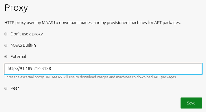
To enable the internal proxy, ensure that the checkbox adjacent to ‘MAAS Built-in’ is selected. This internal proxy is the default configuration.
To enable an external proxy, activate the ‘External’ checkbox and use the new field that is displayed to define the proxy’s URL (and port if necessary).
An upstream cache peer can be defined by enabling the ‘Peer’ checkbox and entering the external proxy URL into the field. With this enabled, machines will be configured to use the MAAS built-in proxy to download cached APT packages.
To prevent MAAS machines from using a proxy, enable the ‘Don’t use a proxy’ checkbox.
NOTE that the proxy service will still be running.
How to set up Network Time Protocol (NTP)
MAAS provides managed NTP services (with Chrony↗) for all region and rack controllers. This arrangement allows MAAS to both keep its controllers synchronised, and keep deployed machines synchronised as well. You can configure NTP on the ‘Network services’ tab of the ‘Settings’ page.
The region controller configures the NTP service to keep its time synchronised from one or more external sources. By default, the MAAS region controller uses ntp.ubuntu.com. Rack controllers also configure the NTP service, synchronising their time with the region controllers. Rack controllers also configure DHCP with the correct NTP information. Any machine on the network that obtains a DHCP lease from MA/snap/3AS will benefit from NTP support.
Setting an external NTP server
External sites, such as an existing NTP infrastructure, can be used directly as a time source for both rack controllers and machines.
You can specify an external site by choosing the NTP server(s) and selecting the ‘External Only’ option. The region controller always uses an external site.
On the ‘Settings’ page, select the ‘Network services’ tab and scroll down to the ‘NTP’ section:
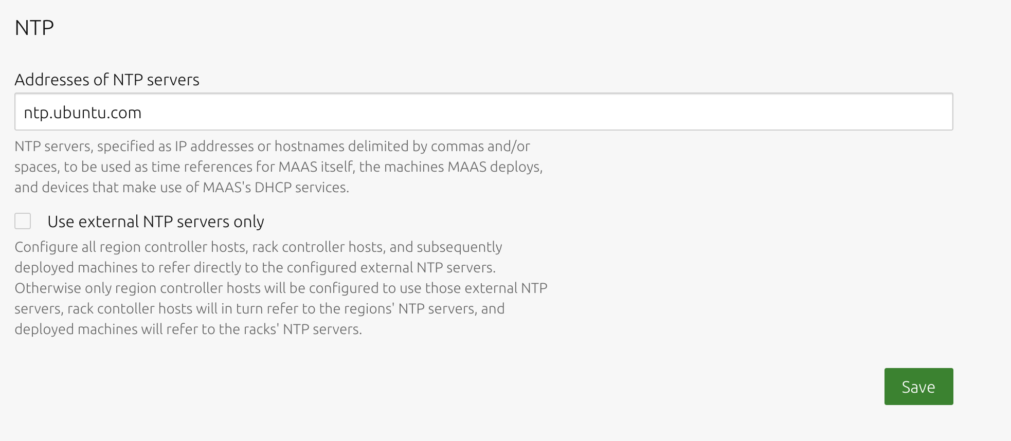
Enter the address of the desired NTP server. Apply any changes by pressing the ‘Save’ button.